
- English
- Español
- Português
- русский
- Français
- 日本語
- Deutsch
- tiếng Việt
- Italiano
- Nederlands
- ภาษาไทย
- Polski
- 한국어
- Svenska
- magyar
- Malay
- বাংলা ভাষার
- Dansk
- Suomi
- हिन्दी
- Pilipino
- Türkçe
- Gaeilge
- العربية
- Indonesia
- Norsk
- تمل
- český
- ελληνικά
- український
- Javanese
- فارسی
- தமிழ்
- తెలుగు
- नेपाली
- Burmese
- български
- ລາວ
- Latine
- Қазақша
- Euskal
- Azərbaycan
- Slovenský jazyk
- Македонски
- Lietuvos
- Eesti Keel
- Română
- Slovenski
- मराठी
- Srpski језик


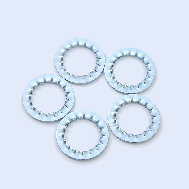
Internal Tooth Lock Washers Black Zinc
The Internal Tooth Lock Washers Black Zinc produced by Xiaoguo® factory can absorb shock forces and dynamic loads during use, preventing the loosening of pump, compressor and engine components, and providing protection for the parts.
Send Inquiry
Product Description
Internal Tooth Lock Washers Black Zinc. The combination of surface treatment and material provides additional advantages.
(1)Outstanding corrosion resistance
The salt spray resistance time of the black zinc coating is typically 72-120 hours, which is several times longer than that of ordinary blackening treatment. Therefore, the Internal Tooth Lock Washers Black Zinc can withstand more demanding humid or mild corrosive environments.
(2)Excellent aesthetics and recognizability
It has a uniform black matte appearance, which not only meets the aesthetic requirements of the equipment, but also serves as a visual identifier on the assembly line, facilitating operators to quickly identify and classify.
(3)Outstanding vibration and impact resistance
After being engaged, the toothed insert can maintain the preload of the fastener in a high-intensity vibration environment, preventing loosening caused by long-term vibration or impact loads.
(4)Reliable electrical grounding performance
It can destroy the non-conductive coating on the contact surface through mechanical means, forming a low-resistance stable conductive connection, ensuring the long-term effectiveness of the electrical equipment grounding system.
(5)Standardization of raw materials and specifications
Mainly made of high-strength spring steel, offering a full range of sizes in both metric and imperial standards.

Core application fields
The Internal Tooth Lock Washers Black Zinc is a choice that combines high corrosion resistance with professional aesthetic appearance. It is an ideal core component in multiple industrial fields with strict requirements for performance and the environment.
(1)Automobile manufacturing
It is commonly used for fastening and anti-loosening in key parts such as engines, gearboxes, and braking systems. It can effectively cope with continuous vibrations during vehicle operation and salt and mud erosion.
(2)Industrial machinery
Suitable for various machine tools, conveying equipment and heavy industrial equipment, it can ensure the long-term stability of the connection during continuous operation and high load, reducing downtime and maintenance due to vibration.

| M2 | 2.2 | 2.34 | 4.20 | 4.5 | 0.28 | 0.32 |
| M2.5 | 2.7 | 2.84 | 5.20 | 5.5 | 0.37 | 0.43 |
| M3 | 3.2 | 3.38 | 5.70 | 6.0 | 0.37 | 0.43 |
| M3.5 | 3.7 | 3.88 | 6.64 | 7.0 | 0.47 | 0.53 |
| M4 | 4.3 | 4.48 | 7.64 | 8.0 | 0.47 | 0.53 |
| M5 | 5.3 | 5.48 | 9.64 | 10.0 | 0.57 | 0.63 |
| M6 | 6.4 | 6.62 | 10.57 | 11.0 | 0.67 | 0.73 |
| M7 | 7.4 | 7.62 | 12.07 | 12.5 | 0.77 | 0.83 |
| M8 | 8.4 | 8.62 | 14.57 | 15.0 | 0.77 | 0.83 |
| M10 | 10.5 | 10.77 | 17.57 | 18.0 | 0.87 | 0.93 |
| M12 | 13.0 | 13.27 | 19.98 | 20.5 | 0.96 | 1.04 |
| M14 | 15.0 | 15.27 | 23.48 | 24.0 | 0.96 | 1.04 |
| M16 | 17.0 | 17.27 | 25.48 | 26.0 | 1.16 | 1.24 |
| M18 | 19.0 | 19.33 | 29.48 | 30.0 | 1.36 | 1.44 |
| M20 | 21.0 | 21.33 | 32.38 | 33.0 | 1.36 | 1.44 |
| M24 | 25.0 | 25.33 | 37.38 | 38.0 | 1.45 | 1.55 |
| Informtion and drawing Provided are reference only | ||||||
Hot Tags: Internal Tooth Lock Washers Black Zinc, China, Manufacturer, Supplier, Factory
Related Category
Send Inquiry
Please Feel free to give your inquiry in the form below. We will reply you in 24 hours.