
- English
- Español
- Português
- русский
- Français
- 日本語
- Deutsch
- tiếng Việt
- Italiano
- Nederlands
- ภาษาไทย
- Polski
- 한국어
- Svenska
- magyar
- Malay
- বাংলা ভাষার
- Dansk
- Suomi
- हिन्दी
- Pilipino
- Türkçe
- Gaeilge
- العربية
- Indonesia
- Norsk
- تمل
- český
- ελληνικά
- український
- Javanese
- فارسی
- தமிழ்
- తెలుగు
- नेपाली
- Burmese
- български
- ລາວ
- Latine
- Қазақша
- Euskal
- Azərbaycan
- Slovenský jazyk
- Македонски
- Lietuvos
- Eesti Keel
- Română
- Slovenski
- मराठी
- Srpski језик


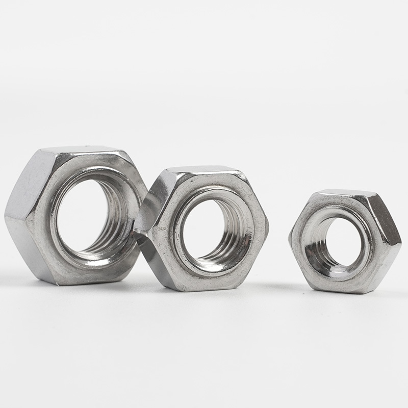
Hex Projection Weld Nuts
Compared to the combination of bolts and washers, Xiaoguo® Hex Projection Weld Nuts are more streamlined and facilitate inventory management. If any interested customers are available, we can offer a portion of them as free samples for preliminary product testing.
Model:JIS B1196-1.1-1982
Send Inquiry
Product Description
The installation of Hex Projection Weld Nuts is mainly accomplished through resistance spot welding. Here is the installation guide.
【1】Welding Preparation
(1)Workpiece Preparation
①Material Requirements: The base material should be a weldable metal (such as low-carbon steel, galvanized steel, stainless steel, etc.), with a thickness usually ranging from 0.5 mm to 5.0 mm.
②Cleaning the surface: Before welding, all contaminants such as oil, rust, paint, and galvanized layers in the welding area of the base material must be removed.
③Processing of locating holes: For piloted nuts (with guide pins), locating holes need to be pre-drilled on the base material.
(2)Welding equipment
①Welding power source: It is recommended to use a medium-frequency inverter direct current welding machine.
②Welding machine capacity: The welding machine must have sufficient power capacity to ensure that the welding parameters are within its normal operating range.

【2】Welding parameter settings
(1)Electrode pressure
Small low-carbon steel welding nuts: 300 - 1,000 psi (approximately 2.1 - 6.9 MPa)
Large welding nuts: 1,000 - 2,000 psi (approximately 6.9 - 13.8 MPa)
Stainless steel welding nuts: 1,500 ~ 5,000 psi (approximately 10.3 ~ 34.5 MPa)
(2)Welding Current
The welding current should be determined through trial welding based on the specifications of the Hex Projection Weld Nuts, the thickness of the base material, and the material. If the current is too low, it will result in incomplete welding; if it is too high, it may cause spatter or welding through.
(3)Welding Time
It is usually measured in cycles. 1 cycle = 1/50 second = 0.02 seconds (for a 50 Hz power supply).

| Mon | M4 | M5 | M6 | M8 | M10 | M12 |
| P | 0.7 | 0.8 | 1 | 1|1.25 | 1.25|1.5 | 1.25|1.75 |
| s max | 11 | 11 | 13 | 15 | 17 | 19 |
| s min | 10.57 | 10.57 | 12.57 | 14.57 | 16.57 | 18.48 |
| H max | 5 | 5 | 6 | 7.5 | 9 | 11 |
| H min | 4.7 | 4.7 | 5.7 | 7.14 | 8.64 | 10.57 |
| d1 max | 6.9 | 6.9 | 8.9 | 10.9 | 12.9 | 14.9 |
| d1 min | 6.7 | 6.7 | 8.7 | 10.7 | 12.7 | 14.7 |
| h max | 0.8 | 0.8 | 0.8 | 0.8 | 1.2 | 1.2 |
| h min | 0.6 | 0.6 | 0.6 | 0.6 | 1 | 1 |
| h1 max | 0.5 | 0.5 | 0.5 | 0.5 | 0.7 | 0.7 |
| h1 min | 0.3 | 0.3 | 0.3 | 0.3 | 0.5 | 0.5 |
【3】Electrode selection and design
(1)Electrode material
CuCrZr: A type of copper alloy with good electrical conductivity and hardness
W/Cu: Higher hardness and better wear resistance
(2)Electrode surface
The electrode surface should be smooth and centered properly to ensure uniform pressure between the Hex Projection Weld Nuts and the workpiece.
Power electrode: It is recommended to use flat-head electrodes.
Lower electrode: It should be equipped with an insulating locating pin. Ceramic or ceramic-coated locating pins are recommended.
(3)Electrode shape and size
The size and shape of the electrodes need to be tailored according to the specifications of the nuts and the welding positions. T
【4】Welding operation steps
(1)Positioning nut: Place the Hex Projection Weld Nuts on the lower electrode positioning pin, align the guide pin with the pre-drilled hole on the workpiece, and ensure that the three welding protrusions make contact with the base material.
(2)Place the workpiece: Place the workpiece on top of the nut, ensuring that the protrusions make a tight contact with the base material.
(3)Apply pressure: Lower the upper electrode, apply the preset electrode pressure, and compress the nut against the workpiece.
(4)Electrical welding: Connect the welding current. The current passes through the three protrusions, and the protrusions heat up and melt to form a weld core.
(5)Pressure retention crystallization: Cut off the current, maintain the electrode pressure for a short period of time, allowing the molten nucleus to cool and solidify under pressure.
(6)Reset completed: Lift the electrode and remove the workpiece.
Hot Tags: Hex Projection Weld Nuts, China, Manufacturer, Supplier, Factory
Related Category
Hexagon Nut
Square Nut
Hexagon Flange Nut
Lock Nut
Cap Nut
Hexagon Slotted Nut
Hand Screw The Nut
Round Nut
Hubs Nuts
T-nut
Reed Nut
Other Nuts
Send Inquiry
Please Feel free to give your inquiry in the form below. We will reply you in 24 hours.